Part 1: Variable Input & Output
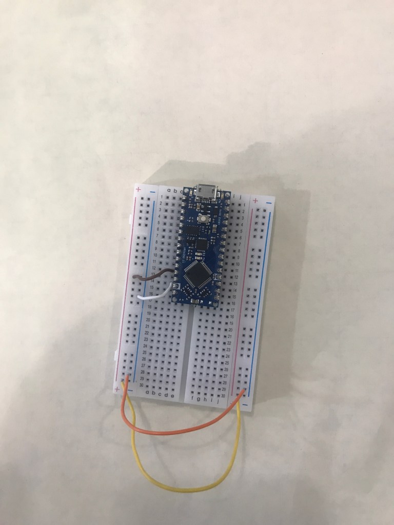
For this part of the assignment, I had to use a potentiometer, a photocell, and two LEDs. However, I decided to do part 2 first, so that is why my potentiometer and photocell are connected by a breakout board. Anyway, the first thing that I had to do was connect power and ground to my microcontroller.
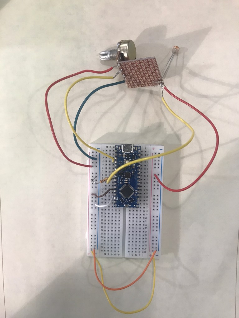
Then I connected my potentiometer and photocell to the breadboard. This is similar to how I connected it in part 2. Photocell is connected to A3 and is connected to power. Then A3 is connected with a resistor to the ground. Meanwhile, the potentiometer is connected to A0 and connected to power and ground.
Then I add the LEDs to the breadboard. I connect the LED to the ground first and then connect it to a resistor and then connect the resistor to pin 2 and pin 3.

Code: https://github.com/Enovai/Object/blob/main/Analog.ino
Video:
Part 2: Interactive Sensor “Box”
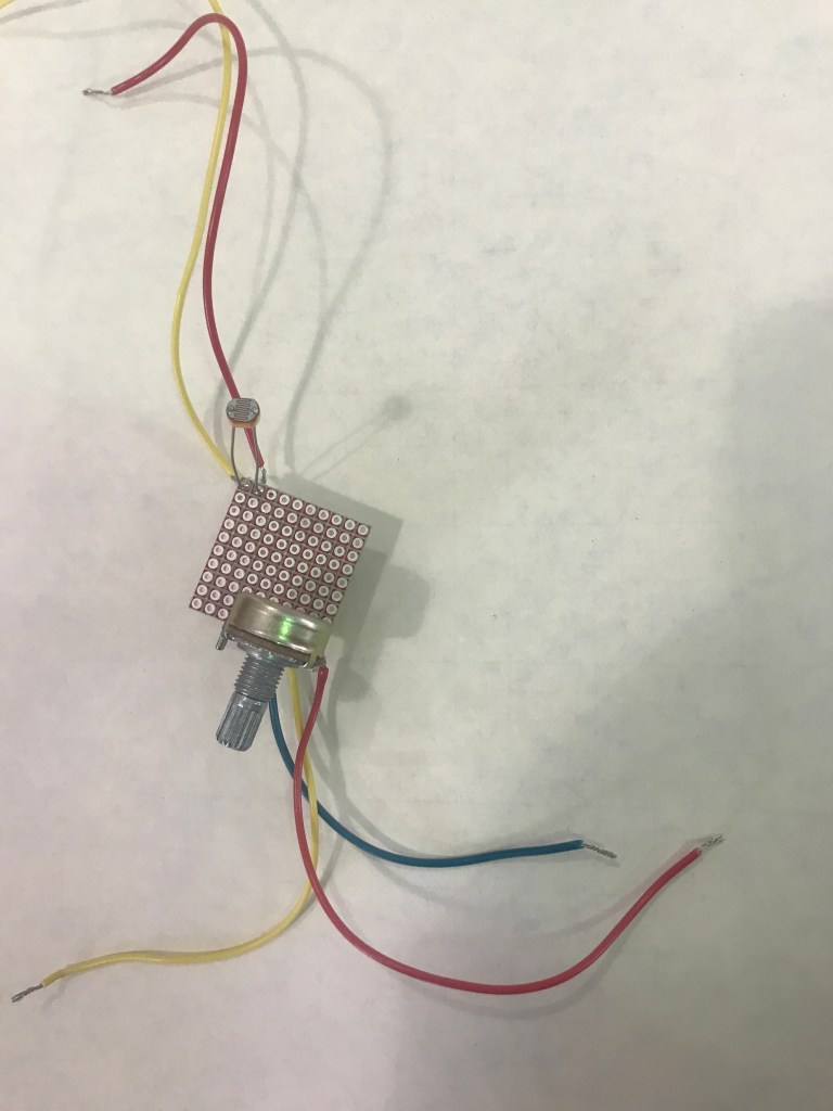
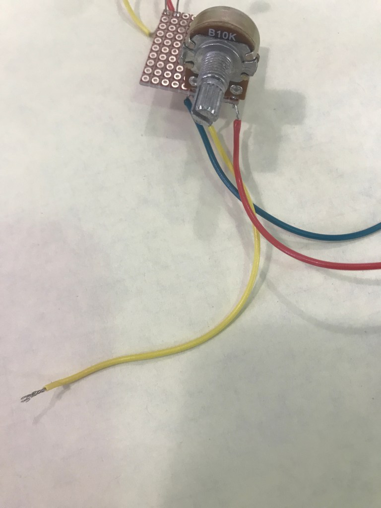
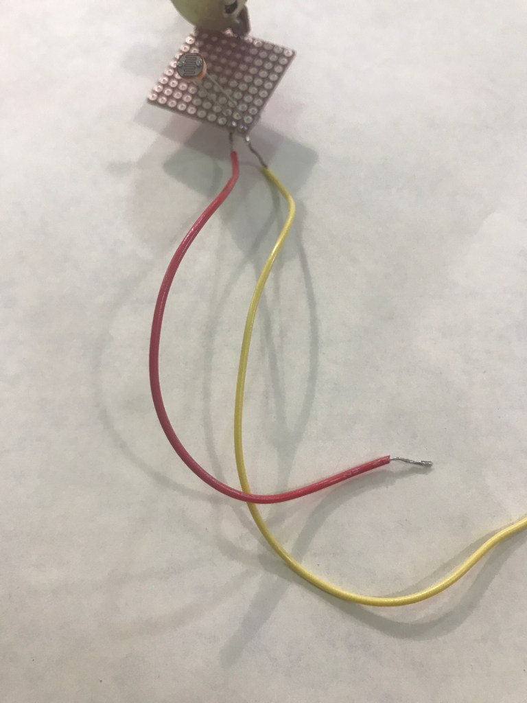
First, I had to decide what type of inputs and outputs did I want for this assignment. For my input, I decided to use a photocell and a potentiometer. I connected both of these inputs on a breakout board so that it’ll be easier to track these inputs inside my box. The potentiometer, it has three wires. The middle one is for a pin. The other two are for ground and power. Meanwhile, the photocell only has ground and power.
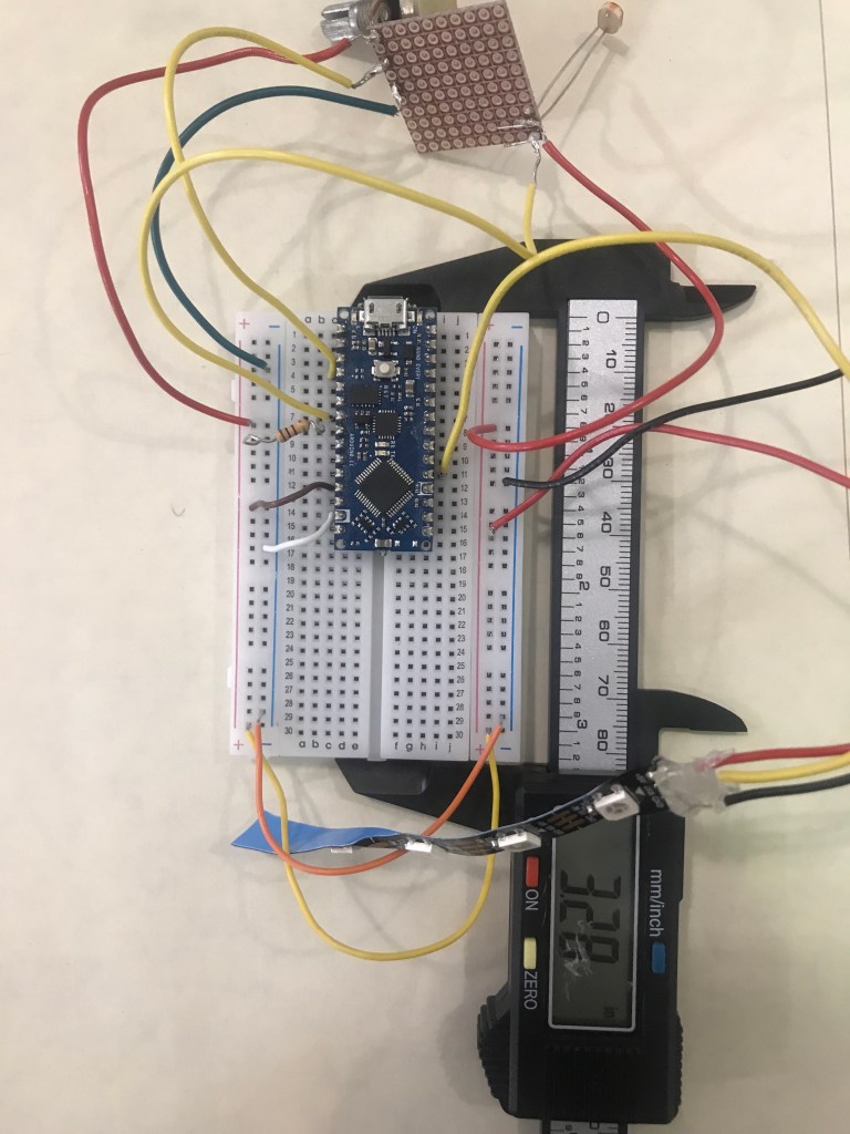
Next, I started working on putting these components onto the breadboard. However, I had to set up the ground and power first and connect those to the microcontroller.

Now, I will connect the potentiometer and photocell to the breadboard. For the photocell, I connected that to A3 for analog input and the other wire to power. For the wire connected to A3, I also added a resistor connected to the ground. For the potentiometer, I connected it to A0 and ground and power.


The last thing that I add to my breadboard would be my output. In this case, I chose a LED strip and connected that to pin 2 and ground and power.

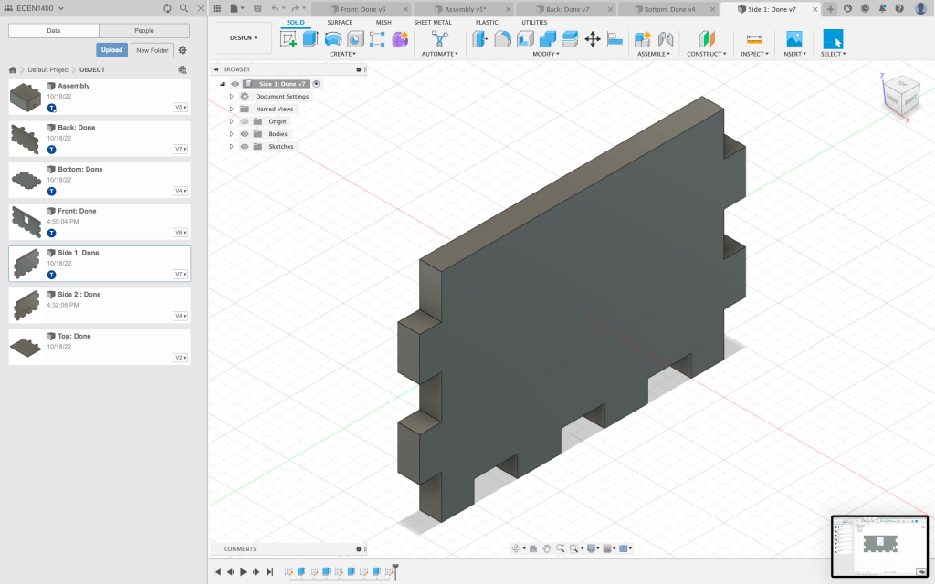
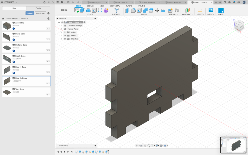
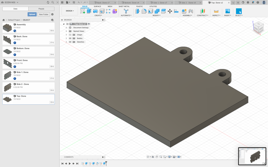
Now that I have all the wiring done, it was at this point when I decided to create my box. I wanted to use the new skill that I learned and decided to 3D print my box. However, that was a big mistake and it took nearly an hour to print each side of the box. It was too late to stop. To 3D print my box, I had to measure my breadboard and its components with a caliper.
After measuring each component, I now have to put that into Fusion 360 and create an actual model of the box that I wanted to create. The box was more rectangular in shape. The holes that I added to the box were where the components such as the potentiometer and photocell will show. I also made a hole where I could connect my USB cord to the microcontroller. The design of the box was made so that I wouldn’t have to glue any of the pieces together. Instead, I can just connect them like a puzzle. Meanwhile, the lid will be held together by a rubber band to make it more flexible when opening and closing the box.

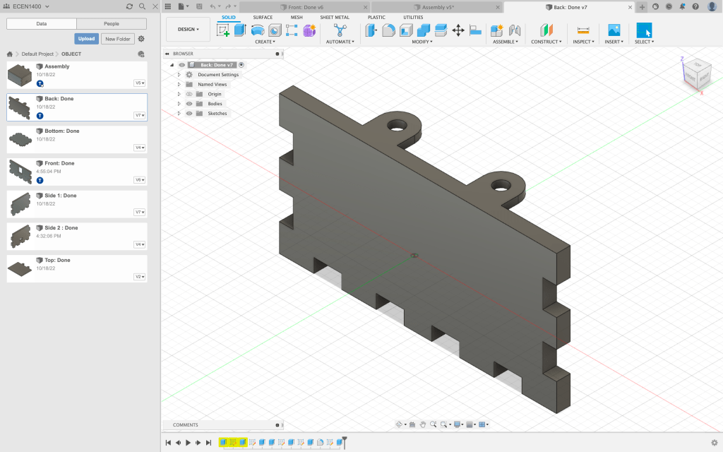

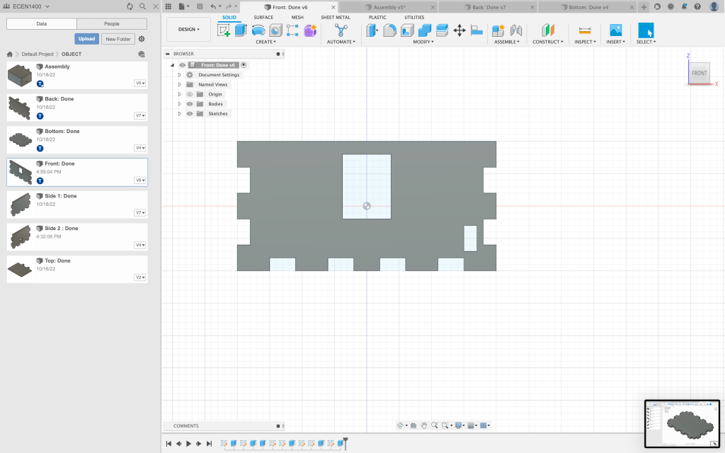
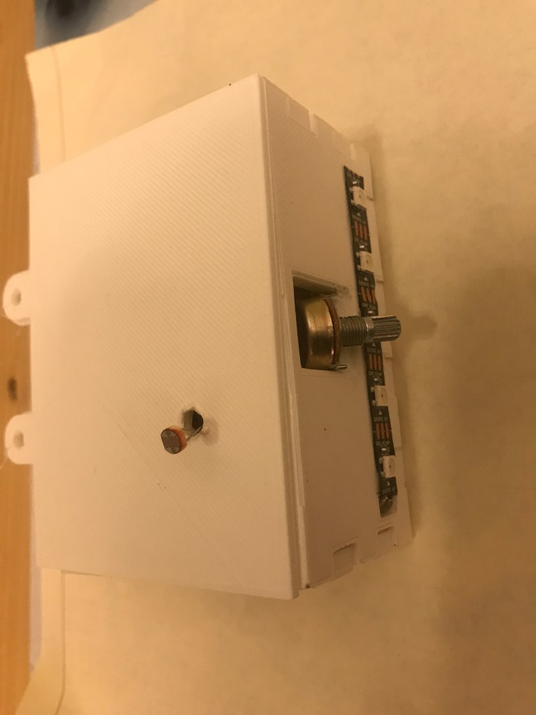
Here is the final look of the box:


Code: https://github.com/Enovai/Object/blob/main/Neopixel___Analog.ino

Leave a comment