Part 1: Digital I/O with LEDs
First, I had to test my board to check if it would follow the example code, Blink. I connected the power and ground of the microcontroller and then connected a resistor to pin 13. This will allow the code to read where the led is as it is related to pin 13 and the resistor shown in the video. To find the resistor value, I had to look up the values for a white led and basically got 100ohms. The equation is as follows: 5V-3V/0.02A=100ohms.
Once I had tested that my board worked and the led worked, I now begin working on adding switches to the board. I had to connect the switch to a pin and a resistor and power. Thus, I connected to switch 1 to pin 2 and switch 2 to pin 4.
Code: https://github.com/Enovai/Object/blob/main/Button_Code_2_.ino
Schematic
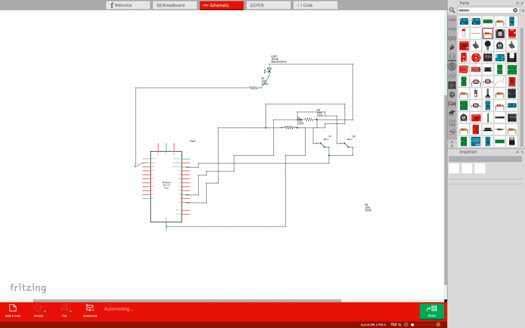
Part 2: Digital I/O with a Programmable LED Strip
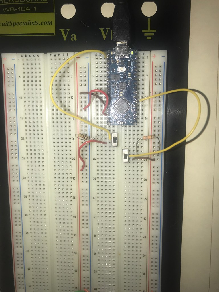
I connected ground to – and power to + from the microcontroller. Then I connected the power and ground to the whole board as shown at the bottom of the breadboard.

Now I connect the switches to the microcontroller. Switch 1 is connected to pin 13 and has a resistor to ground and is connected to power. Switch 2 is similar because it also has a resistor connected to the ground and is connected to power. However, switch 2 is connected to pin 2.
Now I connect the NeoPixel strip to the board. To do that I had to solder the neopixel strip. The black wire is for the ground. The red wire is for power. The yellow wire is for what pin the neopixel strip will be connected to. I also hot glues the wires so that they stay in place.
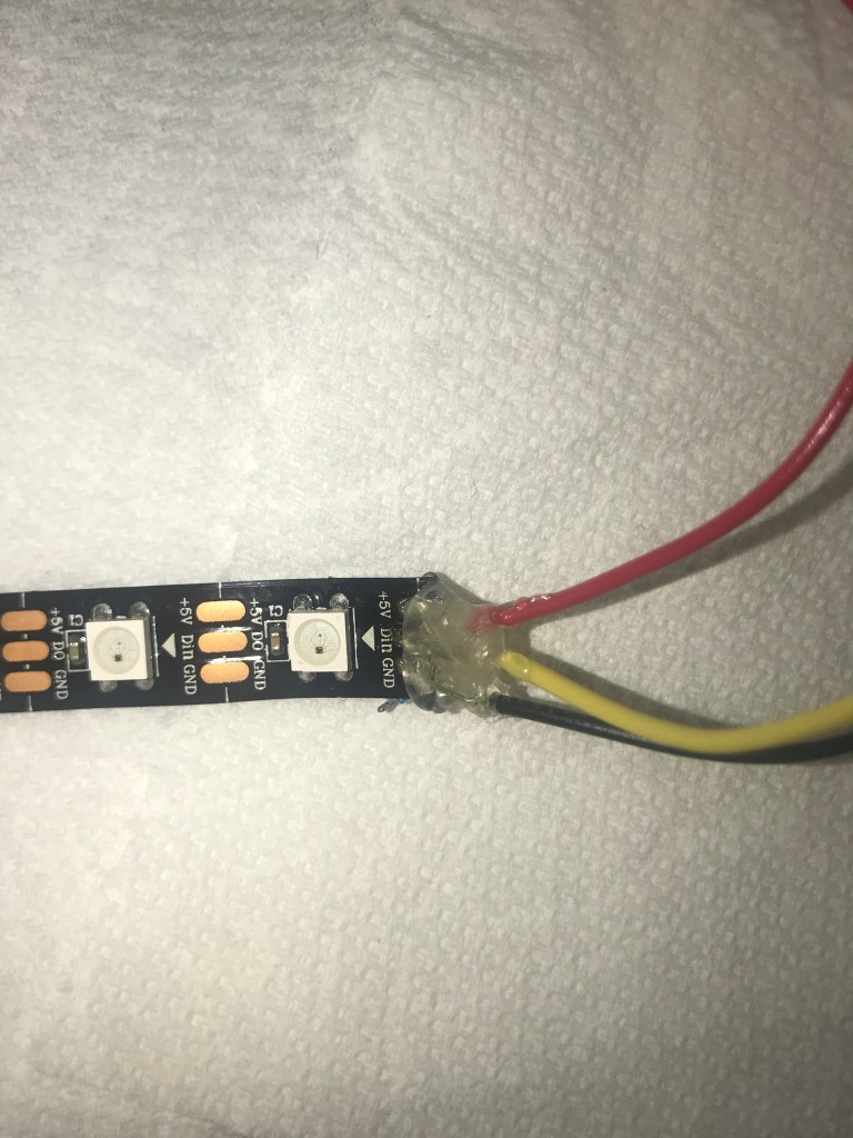
I then connected the yellow wire to pin 8. Below is a video of the two switches and NeoPixel strip.
Code: https://github.com/Enovai/Object/blob/main/Part_2_Code.ino
Part 3: Soldered Breakout Boards
I had to solder my breakout board first before connecting anything onto my bread board. For this, I decided to do a single resistor and led to replicate what was done for the blink program in part 1. I connected the red wire to the end of the resistor and then the black wire to the end of the led. Then I connected the yellow wire to the part between the led and resistor. Just to be noted, there are some holes soldered in because I used too much soldering wire.


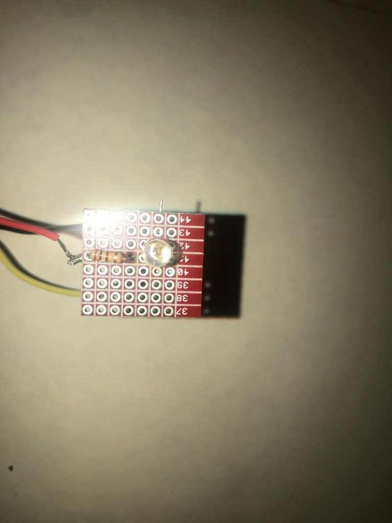
Here is a video of the breakout board using the blink program.


Leave a comment